


The difference between tilting-pad and fixed-pad thrust bearing sets is not that you like more. The key is to see if the bearing shape can be adjusted according to the actual operating conditions. The fixed bushing bearing carries load through a wedge angle which was cut into pad surface when the bushing is made. If the wedge does not match the current speed, oil temperature or load distribution, the bearing will work poorly or break. A Tilting Pad Thrust Bearing Assembly, on the other hand, allows each pad to rotate its pivot. It rotates until the thickness and shape of the oil film meet current operating conditions. Differences between the two devices control load capacity, heat stability, tolerance to deviation, and bearing duration. These effects are difficult to see in still pictures.
This article will explain how to make each setting different in a physical way, how the self-tuning section works, where each setting works well, and what forces you to choose a type.
The Fixed-Pad Configuration: Geometry Set at Manufacture
Fixed-pad thrust bearings-whether tapered, flat with grooves or terraced-give the rotating collar a static surface shape. The shape of oil film thickness shape is determined by the shape of the gasket when leaving the machine tool. For a conical floor design, this means a stable innerto outer conical angle (usually 0.3 to 1.2 per cent of the length of the pad) plus a flat area on the back. Narrow sections produce hydrodynamic pressure. Flat areas spread the pressure across more space. Once the pad is in, the angles can't be changed.
The result of fixed shapes is that the best film shape is suitable only for a set of velocities, oil thickness and loads. At lower velocities, the same cone produces too little pressure because the fluid velocity is too low. At higher speeds, the same cones can exert too much pressure near the front edge. This raises the local temperature and lowers the thickness of the oil layer you need most. As a result, the fixed pad design forces the designer to choose a medium shape to cover the expected range of operating conditions. Bearing will work worse at both ends of the range (Wilcock & Booser, 1957).
How Tilting Pads Work: The Pivot Mechanism
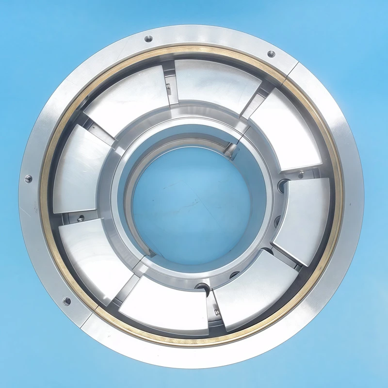
In any pivoted thrust bearing setup, each pad sits at a pivot point. This is somewhere between the middle of the pad and the back edge of it. As the collar rotates, sticky tug sucks oil into the narrow gap. This gap is caused by the tilted position cushions. The resulting oil pressure field generates rotational forces around the pivot. The gasket rotates until the force is balanced by the thrust supported below. The balance occurs when the pad tilts at an angle to shape the thickness of the oil film, providing just enough pressure to maintain the applied load.
The sits of the pivot relative to the middle of the bushing changes the way the bearing works:
Central pivot (50% of the length of the gasket): Under uniform loads, the thickness of the film is approximately equal between the front and back edges. Bearing tends to be neutral and stable.
Eccentric pivot (55–65% of the length of the front to the padding): This makes the film thicker at the back edge than at the front. The carrying capacity of each area has been improved, and the ability to resist heat warping has been improved. But it reduces the minimum film thickness margin when activated. This is the setting used in most factory turbines and compressor bearings (Khonsari & Booser, 2008).
Spherical seat pivot: This tilts the gasket in a circular and lengthwise direction. This causes the bearing handling shaft to misalign without edge loading. This type of thrust bearing is common in large hydrogenerator.
The basic science of tilting-pad operation dates back to Anthony George Maldon Michell's 1905 patent in 1905 and Albert Kingsbury's separate work done independently at the same time. Both showed that a pivoted pad can find the optimal tilt angle of any given speed and load within the range of pivot movement (Ettles, 1978).
Load Distribution: Why Tilting Pads Handle Misalignment
One of the biggest differences between fixed and tilting pads is how they act when the load is not around the bearing circle.
In a fixed gasket bearing with six or eight gaskets, if the rotor deviates from even 0.05–0.10 mm in bearing width, a group of gaskets will bear additional load. Other gaskets have smaller or no loads. Overloaded gaskets have thinner film, higher heat and faster wear. Underloaded gaskets don't help with the load, but they still create friction heat on the cut oil. The imbalance can last unnoticed until a pad gets too hot or the collar gets scratched.
In the tilt pad thrust bearing assembly, the dislocation tilts the heavy pad toward more oil film. Lightweight pads tilt less. Each gasket changes its angle to share the total load more evenly. How to better share the load depends on how much fulcrum is available. Hard wirecontact with the pivot sends some load heterogeneity to the housing. A ball or point contact with the pivot allows the pad to rotate more freely, so it disperses the load better (Etsion & Fleming, 1977).
Numerically, studies using strain sensor pad load cells show that a bias of less than 20% of the pitch of six pads maintains the load difference between pads to about ±15–25% of the average load. However, under the same conditions, the load ratio of a fixed pad is 3: 1 between the most loaded pad and the least loaded pad (Mikula & Gregory, 1984, cited in Khonsari & Booser).
Thermal Behavior and Film Temperature
Fixed gasket bearing is a hot spot where the temperature of local oil film is 30-60 ℃ higher than that of whole oil. It depends on load and speed. On the conical pad, the highest heat region is near the end of the tapered section. This is where the oil film is thinnest. Since taper shape cannot be changed, the hot spot remains in the same position throughout the cycle. When the bearing is heated and cooled several times, it causes a permanent pad warp, known as a heat crown. The center of the pad is larger than the colder edges. This creates a curved bulge that puts more load on the center of the pad (Boyd & Raimondi, 1962). Thermal crowning accumulates over time and cannot be fixed once the elastic recovery limit of the pad material has been exceeded.
On a Tilting Pad Thrust Bearing Assembly, the pad turning part gives a way to adjust on its own. As the gasket heats up and starts to be crowned, changes in surface shape alter the pressure field. This changes the balance of forces around the fulcrum. The pad then moves to a slightly different angle of balance tilt angle. This small, steady adjustment prevents any point on the surface of the pad from staying hot for long. In well-designed tilting sets, the peak and average thermal difference measured is usually 15-30°C. For fixed pad assemblies of the same grade, their temperature is 40-70°C (Ettles, 1991).
Stability: Whirl, Cross-Coupling, and Subsynchronous Vibration
In high-speed spinning machine, the stability of Rotor movement stability is a very important consideration. Fixed-pad thrust bearings, especially those with non-stop loops of earth (no grooves between pads), can increase cross-coupling stiffness. These forces make rotor-bearing systems less stable. These forces come from changes in the stiffness of the oil film around the bearing circle. They can cause vibrations called subsynchronous rotation in machines with bendable shafts, such as gas turbines and centrifugal compressors (Lund, 1964).
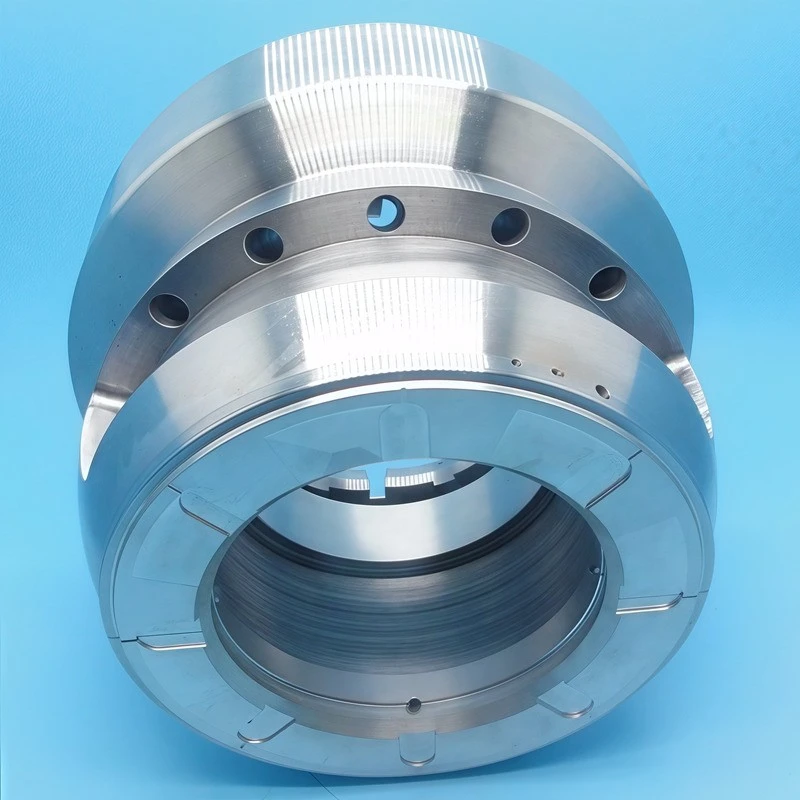
A Tilting Pad Thrust Bearing Assembly naturally stops cross-coupling. This is because each pad acts independently and is not connected to the others. No continuous oil film surrounds one disc after another. Each pad's pressure field ends in a groove between the gaskets. This rupture stops the path that would otherwise send unstable forces around the bearing circle. Therefore, API Standard 617 for process compressors and ISO 10439 for factory turbines require tilting-pad thrust bearings for rotors that rotate beyond the first critical speed. For these rotors, cross-coupling instability is the primary cause of failure (ISO 10439:2019).
Start-Up, Shut-Down, and Boundary Lubrication Wear
Both bearing types have low oil surface contact when starting and closing. This happens when the spin speed is below the level needed to maintain a full oil film. That's the difference in duration between the two settings.
Fixed-gasket bearings, especially conical ground designs with flat areas at the back edge, have direct metal-to-metal contact throughout the flat area during start-up. At low speeds, there are no narrower wedges in the flat area. It is used to spread load at normal speeds. In many start andstop cycles, this contact results in measurable wear on the plane. The speed at which wear occurs depends on the frequency of start, the load applied, and the quality of the low-oil lubricant (ASTM D2266 gives standard test method applicable to the abrasion resistance of the grease here).
Tilting pads has a smaller first contact area when activated. This is because the cushion rests on its pivot, most of its face flat against the collar. The contact area is only the area around the pivot point. This puts the boot load on a small spot rather than spreading it across the width of the pad. It depends on the pad material. Babbitt-lined pads handle this concentrated startup load well because babbitt has low yield strength and great conformability. Steel-backed unlined pads is not handled well. As a result, heavy duty tilting-pad sets are almost always cushioned with a soft top layer (usually tin-based Babbitt, ASTM B23 Grade 2) to survive such conditions (Hamrock et al.., 2004).
Maintenance: Pad Replacement and Leveling Plate Adjustment
The maintenance differences between the two devices are large enough to alter the total cost of bearings over their lifetime at factories that frequently stop working.
Replacement of damaged gaskets in fixed gaskets means removing the entire bearing shell, processing or replacing the damaged gaskets, and then putting the entire gasket back in place with the gaskets to get the center correct again. Total downtime is 4–12 hours. It depends on the size of the machine and how accessible it is.
In modular pivot thrust, you can remove and replace one gasket without moving the others. A The leveling plate under a gasket usually has a shim stacks. These will allow you to adjust the height of each pad after you put a new one in. A well-trained worker can replace a pad (neckline no wider than 300mm) on a medium machine in 45 – 90 minutes. For large hydroelectric thrust bearings with a pad widths of more than 800 mm, replacing the gasket is a planned downtime that will take several days no matter what you set up. But the modular construction of tilt devices makes spare parts easier to manage. You only need to keep a stock of individual gaskets, not the entire bearing shells.
Application Decision Framework
|
Application Characteristic |
Preferred Configuration |
Reasoning |
|
High-speed (>10,000 rpm) compressor |
Tilting pad |
Cross-coupling suppression, thermal stability |
|
Large hydroelectric generator |
Tilting pad (spherical pivot) |
Misalignment accommodation, load sharing |
|
Low-speed (<500 rpm) pump or fan |
Fixed pad (taper-land) |
Simplicity, adequate performance, lower cost |
|
Frequent start-stop cycling |
Tilting pad + Babbitt lining |
Reduced platform-area start-up wear |
|
Continuous-duty steady-state operation |
Either; fixed acceptable if PV < 2.0 MPa·m/s |
Fixed cheaper if conditions stable |
|
Contaminated oil environment |
Fixed pad with grooves |
Grooves flush debris more effectively than tight tilting clearances |
|
Space-constrained installation |
Fixed pad |
No pivot hardware, thinner overall assembly |
Summary
There is a major difference between the thrust bearing assembly of tilt pad and the fixed pad assembly. As the machine runs, each gasket can find its own optimum angle of oil film. This ability provides better load distribution when parts are dislocated, lower peak running temperatures, no rotor vibration cross-coupling forces, and faster replacement of single cushions during maintenance. The drawbacks are higher manufacturing costs, more complex assembly, the risk of dirt clogging pivot gaps, and no benefit at very low speeds when both settings keep a full oil film. The choice between them depends directly on how the machine runs. Work that is fast, hot or biassensitive requires tilt pads. By correctly selecting the shape of the fixed gasket, slow, load stable, and cost sensitive job can be handled well.
References
- Wilcock, D.F. & Booser, E.R. (1957). Bearing Design and Application. McGraw-Hill.
- Khonsari, M.M. & Booser, E.R. (2008). Applied Tribology: Bearing Design and Lubrication (2nd ed.). John Wiley & Sons.
- Hamrock, B.J., Schmid, S.R. & Jacobson, B.O. (2004). Fundamentals of Fluid Film Lubrication (2nd ed.). Marcel Dekker.
- Ettles, C.M. (1978). "The development of a generalized computer analysis for sector-shaped tilting-pad thrust bearings." ASLE Transactions, 21(2), 99–108.
- Ettles, C.M. (1991). "Some factors affecting the design of large thrust bearings." Proceedings of the Institution of Mechanical Engineers, Part J: Journal of Engineering Tribology, 205(2), 87–97.
- Boyd, J. & Raimondi, A.A. (1962). "Application of finite-length journal bearing theory to hydrodynamic lubrication problems." ASME Journal of Basic Engineering, 84(1), 191–202.
- Lund, J.W. (1964). "Spring and damping coefficients for the tilting-pad journal bearing." ASLE Transactions, 7(4), 342–352.
- Etsion, I. & Fleming, D.P. (1977). "A comparison between stiff-pivoted and spring-supported tilting-pad thrust bearings." ASLE Transactions, 20(2), 95–102.
- ASTM B23/B23M-21. Standard Specification for White Metal Bearing Alloys (Babbitt Metals). ASTM International.
- ASTM D2266-18. Standard Test Method for Wear Preventive Characteristics of Lubricating Grease (Four-Ball Method). ASTM International.
- ISO 10439:2019. Petroleum, petrochemical and natural gas industries - Axial compressors. International Organization for Standardization.
- Stachowiak, G.W. & Batchelor, A.W. (2014). Engineering Tribology (4th ed.). Butterworth-Heinemann.