


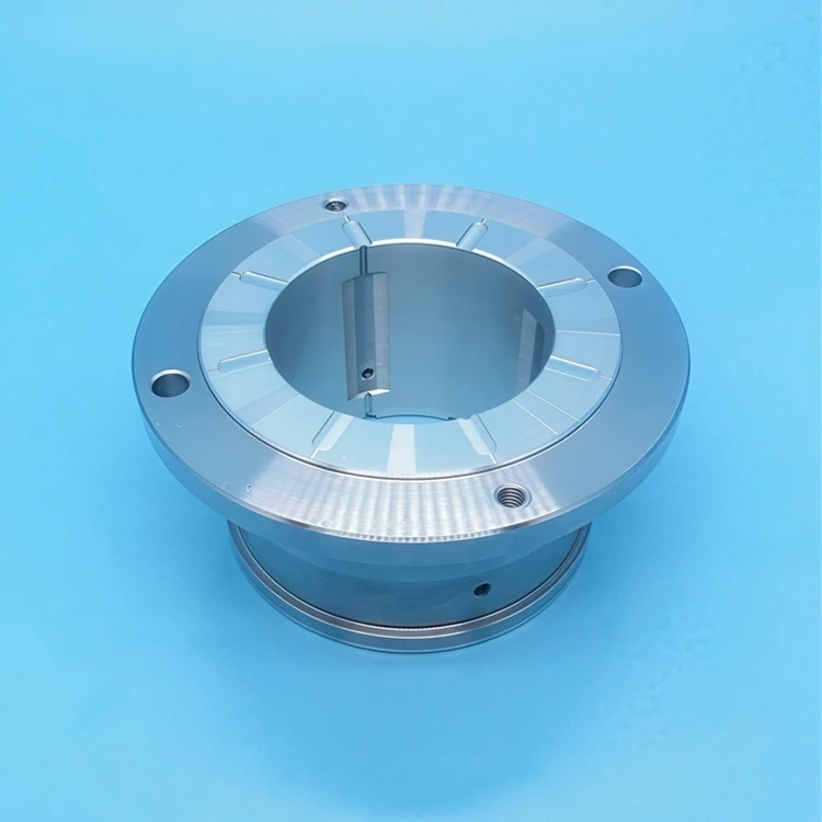
A Taper-land Thrust Bearing is a kind of hydrodynamic thrust bearing with fixed geometry. It has no pivot, no automatic adjustment pad and no automatic tilt adjustment. The bearing carries axial load by using a wedge inlet area machined directly to the bearing surface.
The bearing's pressurization capacity comes from this wedge shape. When the rotating surface moves lubricant into a narrow gap, pressure forms inside the oil film. This pressure supports the axial load and keeps the surface separate during operation.
Since bearings depend entirely on its machined geometry, the dimensions of cones must be carefully controlled. Minor changes in taper angle, film thickness or surface shape can affect pressure generation and bearing performance.
In order to understand how conical thrust bearings work, it is necessary to examine the hydrodynamics of the pressure generated within the lubricating film, rather than simply viewing bearings as components with a a specified load rating.
The Core Mechanism: Hydrodynamic Pressure from a Converging Wedge
Every hydrodynamic fluid film bearing, including journal bearings, tiltpad thrust bearing and tapered ground thrust bearing, has the same bearing capacity as the physical effects described Osborne Reynolds in 1886. When the viscous liquid is dragged through a narrow gap by the movement of two surfaces, pressure inside the fluid membrane increases. This pressure, when spread to the bearing area, supports the load without metal-to-metal contact.
In a Taper-land Thrust Bearing, this narrowing gap is made by fixing geometry rather than moving or adjusting. Each gasket on the bearing ring has two main areas in the direction of rotation.
Taper zone (inlet): The surface is at a small angle to the runways. This creates a gap that narrows as oil is pulled inward by rotation. Much of the hydrodynamic pressure is generated in this region.
Flat (outlet): surface parallel to the runways. This area maintains pressure after it is produced and the oil leaves the pad at the tail edge into drain groove.
The ratio of flat land length to total pad length is generally 0.60-0.70. If the flat ground is too short, there is not enough area to withstand the resulting pressure. If you take too long, taper zone will be too small and pressure will not increase effectively.
The Reynolds Equation Applied to Taper Geometry
The one-dimensional form of the Reynolds equation for an incompressible, constant-viscosity film under steady conditions is:
d/dx (h³ dp/dx) = 6 μ U dh/dx
In this equation, h is local film thickness, p is pressure, mu is dynamic viscosity, U is relative surface velocity, x is coordinates of direction of motion.
For linear conical inlets, h (x) decreases at a constant rate from the thickness of the inlet membrane h1 to the minimum membrane h2 at the cone-land junction. The pressure gradient dp/dx depends on both μU and dh/dx. This has the following direct effects:
• Higher speed increases film pressure and increases load capacity when film thickness is the same.
• Higher viscosity produces the same effect as higher speed.
• A steeper taper does not always improve performance. If the taper angle becomes too large, the pressure builds too close to the inlet and the overall pressure distribution becomes uneven. This reduces the total load capacity.
The optimum cone ratio of h1/h2 of maximum bearing capacity is about 2.2 under laminar flow and constant-viscosity conditions. This means the intake film thickness is about 2.2 times thicker than the minimum film. Specifically, if the minimum film thickness is 15–25 μm, the inlet step height is approximately 33-55 microns. This is a fixed mechanical function, not something that changes in the course of operation.
Geometry vs. Adaptive Tilt: How Taper-land Differs from Tilting-Pad
The main alternative to conical ground design is the tiltpad (Michell/Kingsbury) thrust bearing. In this design, each pad is mounted on a pivot. The gasket can be tilted and angled according to operating conditions and runner motion.
This self-adjusting movement allows the gasket to find the most optimal angle during operation. It helps bearings form a stable oil film across a wide range of speeds and loads.
The difference between the two designs reflects both the advantages and limitations of conical ground bearings:
|
Characteristic |
Taper-land Design |
Tilting-Pad Design |
|
Optimal taper for each load/speed |
Fixed by machining |
Self-adjusted via pivot rotation |
|
Low-speed film generation |
Poor (taper sub-optimal at low U) |
Better (pivot-self-correcting) |
|
High-speed stability |
Excellent (no pivot flutter risk) |
Risk of pad flutter at very high speed |
|
Thermal distortion sensitivity |
Higher (taper geometry changes with thermal growth) |
Lower (pivot re-accommodates) |
|
Manufacturing cost |
Lower |
Higher |
|
Axial stiffness |
Lower (soft entry at trailing edge) |
Higher |
|
Suitable service |
Moderate speed, well-characterised load |
Variable speed, reversible load |
Fixed taper refers to the highest efficiency the Taper-land Thrust Bearing at the design working point. Because speed is much lower than designed, the hydrodynamic film thins and the bearings are lubricated close to the boundary-the mixed-lubrication transition described below.
Load Capacity, Speed, and Sommerfeld Number
Load capacity of a taper-land thrust pad scales with the bearing number (sometimes called the Sommerfeld number for thrust bearings), defined as:
S=μNP(Rc)2S=PμN(cR)2
where N is rotational speed (rev/s), P is mean bearing pressure (load ÷ projected area), R is a characteristic radius, and c is the reference clearance related to h₂. For a given geometry, load capacity is approximately proportional to μNU - meaning bearing capacity scales linearly with speed.
Practical load capacity ranges for taper-land thrust pads in industrial service (Boyd and Rowe, 1982; Wilcock and Booser, 1957):
|
Mean Bearing Pressure |
Typical Service |
|
0.7–1.7 MPa |
Moderate-duty pumps, fans, gearboxes |
|
1.7–3.5 MPa |
High-speed compressors, turbines, axial machines |
|
> 3.5 MPa |
Specialist applications; film reliability risk increases sharply |
If you exceed the limit but do not increase viscosity or speed by the same amount, then the film will collapse and you get boundary lubrication. If you go below the minimum speed, the bearing is too big for the load. This creates a different problem: the oil doesn't move in and sweep the taper zone evenly enough, so the temperature isn't evenly distributed across the width of the pad.
Groove Geometry and Thermal Management
Each taper-land pad is separated from the next by a circumferential drainage groove. The groove has two jobs: it takes away hot oil from the back edge of one pad, and it gives cool inlet oil to the front taper of the next pad. This oil swap is the main way to control heat in a taper-land design. Because taper-land bearings do not have directed lubrication like tilting-pad bearings, so they depend on groove turbulence to mix hot and cold oil before it goes into the next taper.
Groove width is usually 15–25% of total pad pitch. Narrower grooves make the gap between pads smaller, so they use space better. But they also hurt oil mixing and make carry-over temperature bigger. Carry-over temperature is the temperature of oil going into the taper compared to the supply temperature. Ettles (1969) showed that the carry-over fraction can cause 40–70% of the film temperature rise in taper-land designs when running above 50 m/s runner surface speed. So this greatly lowers effective viscosity and then lowers load capacity.
At high peripheral speeds above 60 m/s, viscous heating becomes the main design limit instead of load. Oil supply temperature must usually stay at 40–49°C with ISO VG 32–46 turbine oil. This is to keep peak film temperature below 95–100°C. That temperature is the point where thermal damage to the oil's additive package speeds up.

Low-Speed and Start-Stop Failure Mechanism
The biggest limitation of the conical ground design is the way it works when starting, closing and running at low speeds. Because the hydrodynamic film pressure depends on speed, the average bearing pressure of 2.0 MPa can only 20% 0.3–0.5 MPa at normal speed. If the applied thrust load is bigger than this lower membrane capacity, the minimum film thickness is less than the sum of surface roughness --typically 0.5 to 1.5 μm Ra for ground bearing wheels --and asperity contact occurs.
Repeated starting and stopping cycles under load cause stable wear and tear on the flat surface, which is irreparable. Unlike tiltpad bearings, where a small amount of wear at the pivot can still recenter the pad, wear on the flat area of the conical floor directly reduces the pressure area and then accelerates more damage. The ASTM D-4998 four-ball wear test is commonly used to examine the performance of the oil's anti-wear additives under mixed lubrication starting and stopping conditions. This is because the oil's extreme-pressure additives provide the only load support when the hydrodynamic film is not yet formed.
For machines that often start under load-such as motor driven pumps that cycle multiple times per shift-the option of tilt pads should be considered. Alternatively, the conical ground specification should include a hydrostatic lift system to push oil externally into the film at low speeds.
Practical Application Summary
The bearing concept of terraced thrust bearings is mainly embodied in the following three aspects:
1.Convergent wedge shape-Cut into a taper inlet at h1/h2 arc 2.2, so it generates hydrodynamic pressure through the Reynolds mechanism.
2.Flat ground -60-70 per cent of the length of the gasket-provides the pressurized area for bearing axial load.
3. Drain trough-This provides cooler oil for the next cone and stops the viscosity of the thermal breakdown membrane.
None of the three parameters can be changed per se, as each parameter change affects all three performance values: load capacity, film temperature and minimum film thickness. Therefore, engineers should start with the average bearing pressure at normal speed when selecting a conical ground device for a particular machine. They should then check that the matching Sommerfeld number puts the bearing in a full membrane state. They should then confirm that the start stop that start-stop frequency and lubrication system supply temperature work within fixed geometric limits. This is because, unlike pivot pad design, conical ground bearings cannot repair their owndesign operating conditions.
References
- Reynolds, O. (1886). On the theory of lubrication and its application to Mr. Beauchamp Tower's experiments, including an experimental determination of the viscosity of olive oil. Philosophical Transactions of the Royal Society of London, 177, 157–234.
- Boyd, J., & Rowe, W. B. (1982). Tribology: Principles and Design Applications. Macmillan Press.
- Wilcock, D. F., & Booser, E. R. (1957). Bearing Design and Application. McGraw-Hill.
- Ettles, C. M. M. (1969). Hot oil carry-over in thrust bearings. Proceedings of the Institution of Mechanical Engineers, 184(12), 75–81.
- Hamrock, B. J., Schmid, S. R., & Jacobson, B. O. (2004). Fundamentals of Fluid Film Lubrication (2nd ed.). Marcel Dekker.
- Frêne, J., Nicolas, D., Degueurce, B., Berthe, D., & Godet, M. (1997). Hydrodynamic Lubrication: Bearings and Thrust Bearings. Elsevier.
- Khonsari, M. M., & Booser, E. R. (2008). Applied Tribology: Bearing Design and Lubrication (2nd ed.). Wiley.
- Szeri, A. Z. (2011). Fluid Film Lubrication (2nd ed.). Cambridge University Press.
- ASTM D4998-22. Standard Test Method for Evaluating Wear Characteristics of Tractor Hydraulic Fluids. ASTM International.
- ISO 12168-1:2001. Plain bearings - Static load-carrying capacity of hydrodynamic thrust collar bearings without tilting pads. ISO.
- Stachowiak, G. W., & Batchelor, A. W. (2014). Engineering Tribology (4th ed.). Butterworth-Heinemann.