


Among rotating machines whose axial loads determine the survival of the machine - steam turbines propel the shell, ships launch thousands of tons of thrust from propeller shafts, vertical hydraulic generators carry the full weight of the rotor and the hydraulic pressure of the turbine's wheels - bearings that bear those forces must exceed a set of gaskets in an oil bath. It has to be an assembly of precision fabrication, mounted on a rigid pedestal, which has to be anchored to the base, moving oil, removing heat and remaining within microns of normal structural bending.
A Pedestal Pad Thrust Bearing is one such assembly. Its structural characteristics come not from any single component, but from how all of its components - the base housing, pad carrier, tilt liner, balance connector, oil passages, seal and sensor - maintain the integrity of the oil film throughout the operation as a system. These structural layers are described in the following chapters.

The Pedestal Housing: Foundation and Envelope
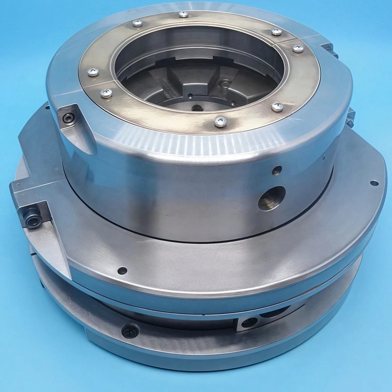
The most obvious part of a Pedestal Pad Thrust Bearing is the base itself - a large casting or welded structure that can perform multiple structural tasks at once. Firstly, it gives the rigid foundation of pad carrier assembly and bolt. Secondly, it forms a lower oil tank in a self-lubricating device or maintains an oil inlet passage in a forced feed system. Third, it has shaft holes with built-in seal housings. Fourth is a bolt flange that fastens the entire bearing to the base or base plate of the machine tool.
The base almost always splits horizontally on the shaft center line, so there is a top half and bottom half connected by precision bolts and dowel pins. This split design is not just for ease of production - it's also for operational purposes. The upper half can be checked for cushions, Babbitt surface inspection and clearance measurement without moving the shaft or removing the lower half from its foundation mounts. The surface of the joint is machined for metal to metal contact and, if required, the entire length of the joint is smoothed to within 0.025 mm. This ensures that the bearing hole remains rounded and aligned when halves are put together.
Cast iron is a common material for substrates because it suppresses vibration well and retains its shape after stress is removed. But welded steel pedestals are increasingly common in large custom designs, where lighter weight and faster delivery are more important. The study in the Journal of Vibration Engineering and Diagnostics showed that cast iron pedestal damped the vibration of structure well in the 100 to 500 Hz range, which matches many common vane and gear meshing vibration sources in steam turbines. This finding allows cast iron to remain useful while welding methods are improved.
Pad Carrier and Tilting Pad Architecture
Inside the pedestal, the pad carrier ring is the mounting frame for the active bearing parts. It's a finely crafted ring piece - either solid or split to match the horizontal connection of the base - that places each tilting pad at the right angle. It also gives a reaction surface driven by the gasket and its supporting link.
Each tilting pad is a fan-shaped section with three functional areas on the surface: an inlet angle or cone at the front edge, pressure from a confluence of hydrodynamic wedges at the middle, and a thin-film pressure drop at the back edge. The pad body is usually steel and the operating surface is lined with white metal alloy - most often tin-based Babbitt that follows ASTM B23 rules - with a finished thickness of 0.75 mm to 2.00 mm. This thickness depends on the size of the gasket and specific loading. Babbitt-to-steel bonds are made by centrifugal casting, static pouring pre-treated with tin, or continuous strip casting for thin use and then pressed.
The fulcrum supporting each pad requires special attention because it is the part that tilts the pad. In a two-way service of a substrate thrust bearing, the pivot is in the center of the substrate, which creates a symmetrical pressure profile regardless of the way the shaft rotates. For one-way machines, which are more common, pivots move toward the back edge, usually at 55% to 60% of the length of the pad arc measured from the front edge. This increases load capacity by about 15% to 20%, with the same pad area and speed as the central pivot design. The pivot part itself can be a hard steel ball, a cylindrical rocker bar, or a wire contact ridge. Selection depends on load size and the extent to which the gasket needs to be tilted.
The Equalizing Linkage: Design load sharing
Even with precise machining, no thrust collar is completely flat and no base housing is completely rigid. If there is no solution, the closest point on the gasket will receive more thrust and fail prematurely. The equalizing linkage - also known as a flat disk system - is a structural solution to this problem.
The concept is mechanically simple. Each pad is located on an upper horizontal plate, which then pushes a lower horizontal plate through contact with a hard rocker. Nearby the top and bottom plates are connected by connecting pins that send movement from one to the other. When a gasket is knocked down by a local collar, its upper plate tilts, and the pin forces a nearby lower plate to tilt the other way. This slightly boosts its matching pads and adds to its load. This chain tilt moves through the entire assembly, with all the gaskets achieving load balance on several axes at turns.
The Turbine Machinery Research Alliance at Texas A&M University's Turbomachinery Research Consortium has published a number of studies on the motion of equalization mechanisms. Their work shows that friction in rocker contact can slow balance by rotating several axes during rapid load changes. The finding has real-world implications: It means that a platform thrust bearing that suddenly changes load - like a ship's propeller hitting a choppy sea or a turbine making an emergency stop - may have a brief platform overload before the balancing mechanism catches up.
Petroleum System Integration in Structures
The pedestal is not just a container for oil - it also helps transport oil. In the design of forced feeding, oil enters through a flanged inlet on the pedestal wall and is then sent to each base feeding point by pouring or drilling an internal channel into the base body. At the end of each channel is a nozzle or hole that injects cooling filter oil into a narrowing gap at the front of the matching pad.
Oil drainage lanes are also carefully designed. After the oil cleans the area through the gasket, the heated oil enters the lower pedestal sump and then flows into the drainage joint, which is usually at the lowest point of the shell. The drain line must be large enough to handle all the oil flow so that the water level in the pool does not rise to the shaft seal area - a common cause of base oil leaks that can be mistaken for seal failure.
For high-speed or heavy duty use, the pedestal may have a water-cooled jacket. These passages are cast into the base wall or covered by bolt-covered panels that move plant cooling water through the pedestal. This draws heat directly from the oil through the base wall, rather than relying solely on external oil cooler. A Pedestal Pad Thrust Bearing running all the time at a specific load above 2.0 MPa can see oil temperature rises of 25°C to 35°C across the pads, and pedestal jacket cooling can lower this by 8°C to 12°C. This helps maintain the thickness of the oil and the strength of the film at the back edge, where it is most dangerous.
Shaft Seals and Pedestal Integrity
A labyrinth or floating ring seal is installed in the housing where the shaft enters or exits the pedestal to prevent oil leaks. These seals also allow for the small radial and axial movements during operation. The seal housings are machined directly to the pedestal end walls, and they have a register diameter that focuses them on the shaft. Labyrinth seal uses a set of circular teeth and matching grooves to make a long, winding leak path. Floating ring seals use a segmented carbon or Babbitt ring that rides on a thin oil film on the surface of the shaft, which seals tighter but also creates more friction drag.
Equipment and Condition Monitoring
In the structure of each modern propeller bearing, there is a built-in method to check its condition. The thermocouple or resistance temperature detector is inserted into selected pads through holes drilled into the pad carrier and the pad wall, and the sensor tips are placed within 1-2 mm of the Babbitt running surface. These sensors can give the earliest practical warning of a film breakdown - a problem known as "wiping" that occurs before a bearing failure badly.
Axial position probes are mounted through the support wall, aiming for the thrust neck, measuring the clearance and tracking long wear and tear of the Babbitt. The steady increase in axial movement under constant load means that the Babbitt becomes thinner and thinner over time. If detected early, planned downtime and replacement of gaskets can be carried out, rather than emergency repairs.
Foundation Interface and calibration
The bolt flange at the base of the base is a structural connector connecting the base or bottom of the machine. This flange is machined flat and often has jack screw holes for vertical adjustment during calibration. The bolting pattern is designed to maintain the vertical weight of the pedestal and the horizontal reaction forces that occur when thrust from the spinning collar passes through the pad and into the base structure.
Check the alignment between the pedestal and shaft before installing, then check from time to time using precision dial indicators or laser alignment tools. The pedestal must align the gasket surface at a right angle to the axis, and tolerance is usually a fraction of the thickness of the minimum oil film - often 0.025 mm or better in the middle radius of the gasket. Reaching this tolerance requires not just accurate machining of the pedestal, but also a foundation that does not sink or bend under load, a requirement that is fed back into the civilian design of machine support structures.
Abstracts
The structural characteristics of propelling bearings with cushions constitute a connecting system. The base is rigid and aligned. The carrier ring places the pad in the correct position. The gasket produces a hydrodynamic film through its fulcrum and Babbitt surface. The equalizing linkage spreads the load. The internal oil passages and cooling sleeve control the temperature. Seals leave the oil inside. Built-in sensors provide a steady stream of bearing health data for operators. Each component helps bearings maintain a micron-thin film of oil under tons of load - a structural achievement that makes possible kilowatt turbines, deep-sea propulsion systems and industrial compressors that support modern power generation and heavy manufacturing.
Reference
Texas A&M Turbomachinery Research Consortium. Static force analysis and Computational model of Self-Equalizing Tilting Pad Thrust Bearings. TRC-B&C-01-19, 2020.
ASTM International. ASTM B23-20: Standard Specification for Alloys of White Metal Bearing Alloys (Known Commercially "Babbitt Metal"). 2020.
Springer Nature. "Experimental Measurement of Oil Film Thickness Distribution in Tilting-Pad Thrust Bearings Using Ultrasonic Methods." Journal of Vibration Engineering and Diagnostics, Vol. 9, 2021.
American Society of Mechanical Engineers (ASME). Calculation and analysis of thrust bearing the Equalization Behavior of tilt pad. ASME Turbo Expo Essays, GT2019-90504.