


In industrial rotary machinery - turbines, generators, large engines, marine propulsion shafts and high-speed compressors - bearing temperatures are the most direct indicator of impending failure. Even if the temperature is 10°C above the established baseline, it is often an indication that the lubricating film is degrading, or that the load distribution has shifted, or that contaminants have entered the clearance area and are wearing down the bearing surface. For decades, plant operators relied on external sensors mounted on bearing housing to detect these changes. But the limitations of this approach are well known: external sensors can record temperature increases only when the bearing has reached a critical state inside. The Temperature Probe Combination Bearing combined bearing is a kind of design that integrates temperature sensing element directly into bearing structure, usually inside the Babbitt lining.
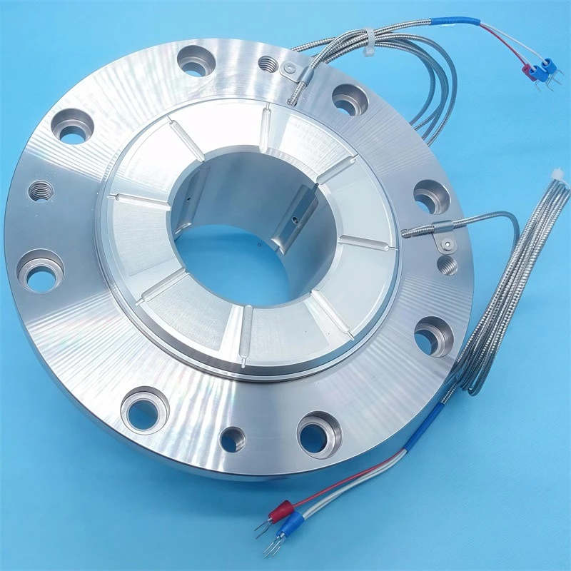
The Anatomy of an Integrated Probe Bearing
The structural basis of a Temperature Probe Combination Bearing is a standard hydrodynamic bearing --whether axle neck or thrust structure --modified to receive one or more temperature sensors within its body. In a typical journal bearing housing, a small diameter hole is drilled radial from the outer surface of steel backing and extended to within 1-2 mm of the Babbit-to-Steel connector. In thrust bearing pads, the hole emerges from the back surface of the liner and terminates at a similar depth under the white metal running surface. Sensors-most commonly resistance temperature detector (RTD) or a thermocouple-are inserted into the hole, and springs are then applied to the bottom of the hole, or glued together a thermally conductive compound.
The key design objective is to approach the heat source without mechanical interference. The sensor tip must be close enough to the Babbitt surface to detect temperature changes in seconds rather than minutes, but it must never penetrate the Babbit layer itself, as any sensor intrusion into the loaded white metal can create a stress concentrator that can cause fatigue cracks under cyclic loading. Standards such as API 670, published by the American Petroleum Institute, state that the tip of a sensor should normally remain between 1.0 and 2.5 millimetres from the Babbitt surface. The exact depth depends on pad thickness, expected thermal gradient and the response time required by the monitoring system.
How the Sensors Work: RTDs and Thermocouples
Two sensor technologies dominate the measurement of bearing temperature, and their working principles are completely different.
Resistance resistance temperature detector takes advantage of the good characteristic relationship between metal resistivity and temperature. Sensor elements --most commonly fine platinum wire or thin platinum plating on ceramic substrates --have resistance that rises almost linearly with temperature. For a Pt100 RTD, an industry-standard configuration, sensors display resistance of 100 ohms at 0°C and about 138.5 ohms at 100°C. The monitoring system sends a small excitation current through the element, measures the resulting voltage drop, calculates the resistance and then converts it into a temperature reading using a standardized calibration curve under IEC 60751. RTD is preferred when measurement accuracy and long-term stability are most important; their drift over successive years of service is usually less than 0.1°C.
A thermocouple works as a Seebeck effect: when two different metal wires are connected at the measuring junction, and the temperature at that junction is different from that at reference junction on the measuring instrument, a voltage proportional to the difference in temperature occurs throughout the circuit. In bearing applications, the most common type is the K-type thermocouple. It pairs chromium (nickel-chromium) with aluminum (nickel-aluminum), producing about 41 microvolts per degree Celsius at temperatures of interest. Thermocouples are less accurate than RTD --the tolerance of a Class 1 K-type thermocouple at bearing operating temperature ± 1.5 ° C --but they are more robust, can handle higher temperatures and respond more quickly because they make sensing knots physically smaller than the smallest practical RTD element.
In a study published in Lubricant, Laubichler and colleagues at Graz University of Technology showed that K-type thermocouples embedded in the bearing shells of heavy diesel engines could reliably detect temperature variations of less than 0.4°C, in combination with data-driven prediction models. This proves that if the sensor position and signal are handled correctly, the a thermocouple's modest precision is sufficient to complete the statusmonitoring task.
Wiring, Signal Transmission, and Noise Immunity
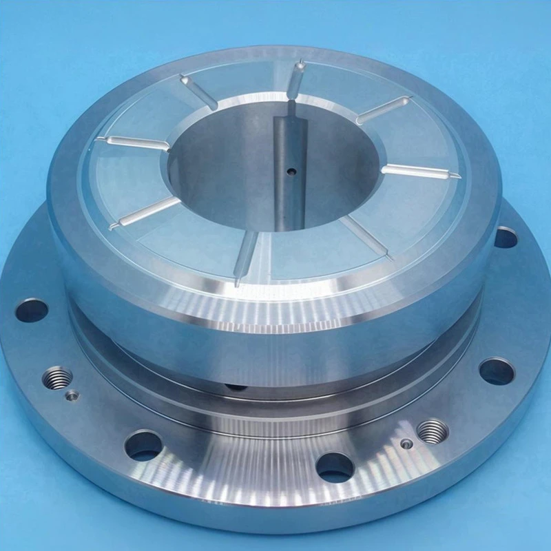
The temperature signal produced by the sensor tip inside the temperature probe bearing must be transmitted in an environment that is not conducive to low-level signal. The wire bundle passes through the bearing housing - usually through a specialized conduit or cable gland - and out of the junction box mounted on the outside of the machine. From there, it connects to field wiring that connect to the control room or local machinery protection cabinets.
Lines matter. RTD usually uses a three-or four-wire device to compensate for the resistance of the wire itself. Otherwise, the resistance will increase the offset error as the length of the cable increases. In a three-wire RTD circuit, two wires carry excitation current and three wires provide voltage sensing paths. This allows the monitoring system to subtract lead resistance from the overall measurement. Four-wire setup, used for the most precise installation, completely eliminateswire errors, but requires more conductors per sensor.
Thermocouple circuits requires the wire to be made of thermocouple-grade material. Ordinary copper wire adds parasitic knots to each joint, which disrupted the measurements. Extended lines must also be kept away from electromagnetic interference sources, especially inverter drive cables and largecurrent conductors. This is because the microvolt-level thermocouple signal easily pick up inductive noise. Shielded, twisted-pair cable and shielding single point grounding are standard practice.
What Temperature Data Reveals
The raw temperature values from the temperature probe combination bearings are useful, but the diagnostic value lies in the pattern over time. Continuous monitoring of three temperature behaviors:
Baseline is set for steady operating temperature at known load and velocity. Any upward drift of the baseline over a period of weeks or months may indicate gradual wear and tear of bearings, oil degradation or contamination of cooling systems. All these developments are slow and require systematic intervention.
The temperature difference between the gaskets of the multi-gasket thrust bearing or between the loaded and unloaded halves of the journal bearing bearing indicates load distribution problem. If, in thrust thrust bearing the temperature of a single liner is 5°C to 8° C C higher than that of an adjacent liner, this strongly indicates local overload. This may be due to a thrust collar misalignment or problems with the bearing balancing linkage.
The speed at which temperatures rise during transient events --start, load change or emergency shutdown --provides the earliest possible warning of acute problems. Rapid temperature spike are defined as increases of more than 2°C per second for large bearings and more than 5°C per second for small bearings, which almost always mean contact between metals. Therefore, this requires immediate load reduction or tripping. API 670 stipulates that machinery protection systems must be able to detect and announce such an ascent event within a second of sensor's response.
Alarm Architecture and Plant Integration
A properly implemented Temperature Probe Combination Bearing installation sends data to a tiered alarm system. The first stage-usually set at 10 to 15 degrees Celsius above normal working temperature-triggers an advance warning. This will prompt the operator to investigate, but will not automatically change the operation of the machine. The second layer is set at the maximum continuous temperature allowed for bearings specified by the original equipment manufacturer. This will trigger an alert that may initiate automatic load reduction. The third and highest tier is set at the emergency travel temperature, beyond which irreversible damage to Babbitt would occur immediately. This order machine shutdown immediately.
Modern monitoring systems combine bearing temperature data with vibration, axial position and lubrication condition data. This gives a multi-parameter view of machine health. Temperature rises that occur as the amplitude of vibration increases usually point to mechanical problems --such as imbalances, dislocations or loose bearings. However, if there is no corresponding vibration change, the temperature increase is more likely to point to lubrication or cooling system problems. As a result, this multiparameter correlation greatly reduces false travel and unnecessary downtime.
Maintenance and Reliability Implications
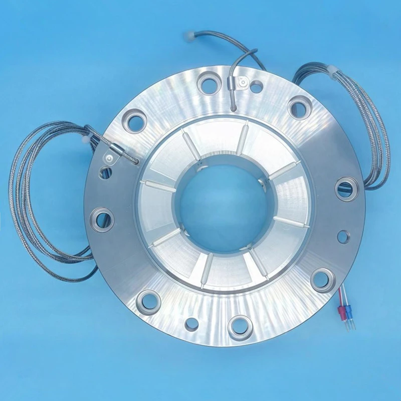
In addition to the protective function, temperature data collected by the instrument bearings support predictive maintenance strategies. Historical temperature trends, when associated with maintenance records, allow reliability engineers to estimate residual bearing life. They can then arrange for replacements during planned downtime, rather than responding to an unplanned glitch. The additional cost of putting a temperature probes during bearing manufacture or repair - typically 5% to 15% of the bearing's base cost - is recovered many times over by avoiding a catastrophic bearing failure. In large turbines or generators, such failures can cause downtime costs of more than $100,000 a day.
The ability to inspect bearings from central control rooms or even off-site monitoring centres has shifted from convenience to operational necessity as industrial facilities adopt more automated and remote operations-a trend accelerated by workforce challenges, as successive reports from the International Energy Agency and other energy sector agencies show. temperature probe combination bearing is the basic sensing element to realize remote monitoring.
References
1. American Petroleum Institute. API Standard 670: Machinery Protection Systems. 5th Edition, Washington, DC: API Publishing Services, 2024.
2. Laubichler, C., Kiesling, C., Marques da Silva, M., Wimmer, A., & Hager, G. "Data-Driven Sliding Bearing Temperature Model for Condition Monitoring in Internal Combustion Engines." Lubricants, Vol. 10, No. 5, Article 103, 2022. DOI: 10.3390/lubricants10050103.
3. International Electrotechnical Commission. IEC 60751: Industrial Platinum Resistance Thermometers and Platinum Temperature Sensors. IEC, 2022.
4. International Energy Agency (IEA). World Energy Employment 2023. Paris: IEA Publications, 2023.